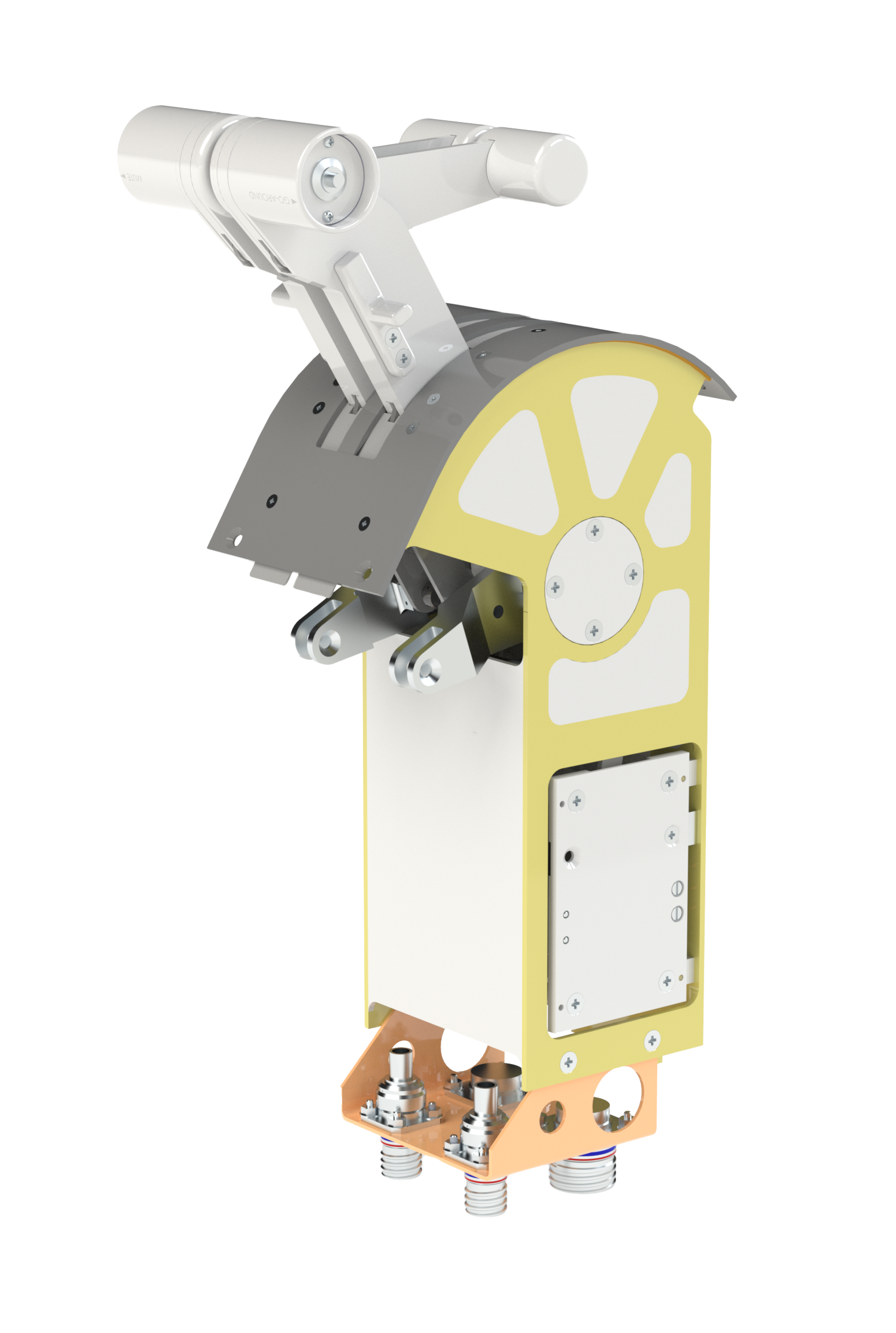
Throttle Quadrants

We tailor the design and testing of our throttle quadrants to suit each unique application. Over the years, we've provided custom aircraft throttle quadrants for a wide range of aircraft, including commuter aircraft, executive aircraft, helicopters, and specialized applications such as the US Navy PHM, Boeing Jet Foil, US Navy LCAC, and USMC LVTP-7 gear section quadrant. 

tailored with precision

Our aircraft throttle quadrants are tailored with precision for any aircraft application.


Ergonomics

  • Knob size (shape fairly standard per FARs) 
  • Go-around switch location 
  • Friction (wheel, lever, or constant, materials) 
  • Detent type (lift buttons/knobs, lift lever, push to side) to side) 
  • Power/condition lever length 
  • Reverse method ((T/R or reverse ppp)rop.) 
  • Visual position indicators (engraving, edge-lighted panel – NVG compatible)


Throttle-Quadrant

Durability

  • Housing (typically rubber mold casting) strength to provide mounting/load path for all components 
  • Levers (machined, square tube) 
  • Knob material properties (Typically composite Molded or Knob material  properties (Typically composite. Molded or machined. Good thermal properties, degradation resistant, Material strength for mounting inserts and constant use) 
  • Switch selection criteria (cycles rating contact type) Switch selection criteria  cycles, rating, contact type) 
  • Switch bank actuation mechanism 
  • RVDT/Potentiometer life 
  • Friction material life


Output

  • Mechanical through clevis to push-pull rods or cables (must maximize mechanical advantage and minimize system friction) 
  • Electro-mechanical (switch banks for discreet position signals, not FBW) through rods, cables and connectors 
  • FBW w/ Mechanical Back-up (must synchronize) mechanical output and electronic signal) 
  • FBW – Potentiometers, RVDTs. (Must consider Potentiometers, RVDTs. (Must consider tolerances, application, redundancy) 


Reliability & Maintainability

  • Past design experience used to meet customer specifications. 
  • MTBF, MTBUR MTBUR 
  • Met by choice of materials, switches and design/interface of dynamic components 
  • Plug & Play TQA for easy installation/rigging/removal 
  • Optimize on previous design experience Optimize on previous design experience 
  • Modular assembly 
  • Minimize need for special tools 
  • ATP equipment specific to product 


Weight

  • Always a balance between operational requirements functional requirements and requirements, functional requirements and environmental requirements 
  • Goal is maximum strength minimum weight Goal is maximum strength, minimum weight 
  • Some flexibility with castings (style, wall-thickness) and materials 


Environmental Considerations

  • Military (stringent for operational exposure) 
  • Commercial (stringent for dispatch rate) 
  • General Aviation (stringent for dispatch rate) 
  • Helicopter (vibration) 
  • Installation location 
    • Protected cockpit Protected cockpit 
    • Will not be used as a step? 


Throttle Quadrant Benefits/Applications

Mechanical

In our mechanical throttle quadrants, precision engineering meets robust construction to provide tactile control and responsiveness for critical flight applications, ensuring safety and performance.

Electro-mechanical

Our electro-mechanical throttle quadrants seamlessly integrate electronic precision with mechanical reliability, offering advanced fly-by-wire control systems to meet the most demanding aviation requirements.

FBW with Mechanical Back-up

Our FBW (Fly-By-Wire) with mechanical back-up throttle quadrants combine cutting-edge electronic control with robust mechanical systems, ensuring aircraft safety and performance even in emergency situations.

Completely FBW

Our completely FBW (Fly-By-Wire) throttle quadrants represent the pinnacle of modern aircraft control, providing precise, reliable, and highly responsive performance, enhancing the flight experience and pilot confidence.


Flight Control Products